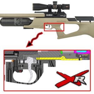
THE BROCOCK XR SERIES RIFLE
Disassembly Guide
On this Page
- Tools you will need
- Contents list
- Further videos
- Removing the stock
- Degassing the rifle
- Removing the barrel and should assembly
- Removing the trigger guard and safety
- Removing the regulator and housing/cylinder
- Disassembling the regulator housing
- Disassembling the bottle regulator
- Disassembling the cylinder
- Disassembling the cylinder regulator
- Removing trigger and trigger sears
- Removing the hammer assembly
- Removing cocking arm and pellet probe
Introduction
BRK Brocock air rifles are engineered to the highest standards, but like anything else, they require repairs and servicing work to be carried out both in and out of warranty.
The aim of this guide and the accompanying videos are to help you undertake work on the BRK Brocock XR series of rifles. Although the rifle in this video is the BRK Sniper XR, the information is relevant to all XR series rifle. Only the stock, barrel length and air bottle options differ. Where components on the Ranger XR, Atomic XR, Commander XR and Concept XR differ, these differences will be explained.
Compressed air is dangerous. You should only use this guide if you are a qualified and experienced gunsmith used to working with compressed air. Before you carry out any work on a BRK XR, or any PCP air rifle for that matter, you must ensure it is not cocked, not loaded and empty of air.
Tools You Will Need
- Long nose pliers
- Open end 22mm spanner
- 8mm spanner
- 3-pin anti-tamper tool
- Regulator removal tool
- Flat bladed screwdrivers: 3mm, 6mm and 10mm
- Allen keys in mm: 0.89, 1.5, 2, 2.5, 3, 4, 5
00:15 Contents List
O-Ring Sizes: Ghost
| PART NO. | DESCRIPTION | CODE | QTY |
|---|---|---|---|
| 3 | o ring Ø13x1.5 - NBR 70Sh | D3OR13X1.5N70 | 2 |
| 4 | o-ring Ø14.5x3 - NBR - 90Sh | OR14.5X3N90 | 1 |
| 7 | o-ring Ø4x1.5 - NBR - 70Sh | D3OR04X15CO | 1 |
| 14 | o-ring 006 - Ø2.9x1.78 (2012) - urethane | D3ORURA06FV | 1 |
| 16 | o ring Ø15x2 - NBR 70Sh | D3OR15X02CO | 3 |
| 19 | o-ring Ø9x1.5 - NBR - 70Sh | BC0R9X15N70 | 1 |
| 20 | o-ring Ø17x1.5 - NBR - 70Sh | OR17X1.5N70 | 1 |
| 23 | o-ring 004 ( Ø1.78x1.78 ) - NBR - 90Sh | D3OR004N90 | 1 |
| 32 | o ring 617 ( Ø17.86x2.62 ) -NBR - 70Sh | D3OR70617MV | 1 |
| 35 | o-ring 007 ( Ø3.68x1.78 ) - NBR - 90SH | OR007N90 | 1 |
| 36 | bonded dowty seal M12 - 867 | BOSEM12867 | 2 |
| 37 | o-ring Ø9.3x2.4 - NBR - 90Sh | OR93X24N90 | 1 |
| 39 | o-ring 006 - Ø2.9x1.78 (2012) - urethane | D3ORURA06FV | 1 |
| 42 | dowty seal self centering 1/8 bsp | D3DOSE18NCO | 3 |
| 130 | o-ring Ø4.1x1.6 - NBR - 70Sh ( cal. 0,177" ) | OR4.1X1.6N70 | 1 |
| 130 | o ring 009 - Ø5.28x1.78 -NBR-70Sh ( cal. 0,22" ) | OR009N70 | 1 |
| 130 | o-ring Ø6.1x1.6 - NBR - 70Sh ( cal. 0,25" ) | OR6.1X1.6N70 | 1 |
| 130 | o-ring Ø7.5x1.5 - NBR - 70Sh ( cal. 0,30" ) | D3OR75X15N70 | 1 |
| 133 | o-ring 813 - NBR - 70Sh | D3OR813N70 | 2 |
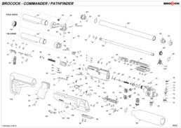
O-Ring Sizes: Commander/Pathfinder
| PART NO. | DESCRIPTION | CODE | QTY |
|---|---|---|---|
| 7 | o-ring Ø3x1.5 - NBR - 70Sh | BCOR31570 | 1 |
| 19 | o-ring - Ø5x1.5 - NBR - 70Sh | D3OR05X15CO | 2 |
| 22 | valve seal Ø4.5 BRK (12 ft/lbs ) | BCVASE45 | 1 |
| 22 | valve seal Ø5.1 BRK ( 0,22 - FAC ) | BCVASE51 | 1 |
| 22 | valve seal Ø5.8 BRK ( 0,25 - FAC ) | BCVASE58 | 1 |
| 23 | o-ring Ø9x1.5 - NBR - 70Sh | BC0R9X15N70 | 1 |
| 28 | o-ring Ø17x1.5 - NBR - 70Sh | OR17X1.5N70 | 2 |
| 30 | o-ring Ø4x1.5 - NBR - 70Sh ( cal. 0,177 ) | D3OR04X15CO | 1 |
| 30 | o-ring Ø5x1.5 - NBR - 70Sh ( cal. 0,22 ) | D3OR05X15CO | 1 |
| 30 | o-ring Ø6x1.5 - NBR - 70Sh ( cal. 0,25 ) | D3OR06X15CO | 1 |
| 31 | o-ring Ø11x1 - NBR - 70Sh ( Ø13 rod barrel ) | BC0R11X170 | 2 |
| 31 | o-ring Ø9 x1-NBR-70Sh ( Ø11,5 rod barrel ) | BC0R9X170 | 2 |
| 64 | o-ring 020 ( Ø21.95x1.78) - NBR - 70Sh | BCOR020N70 | 2 |
| 69 | o ring 019 ( Ø20.35x1.78 ) -NBR-70Sh | OR019N70 | 1 |
| 71 | o-ring 006 - Ø2.9x1.78 (2012) - urethane | D3ORURA06FV | 1 |
| 79 | o ring 617 ( Ø17.86x2.62 ) -NBR - 70Sh | D3OR70617MV | 1 |
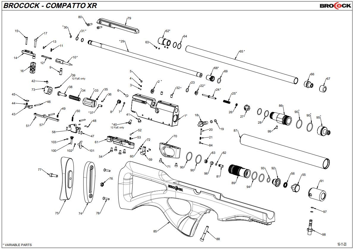
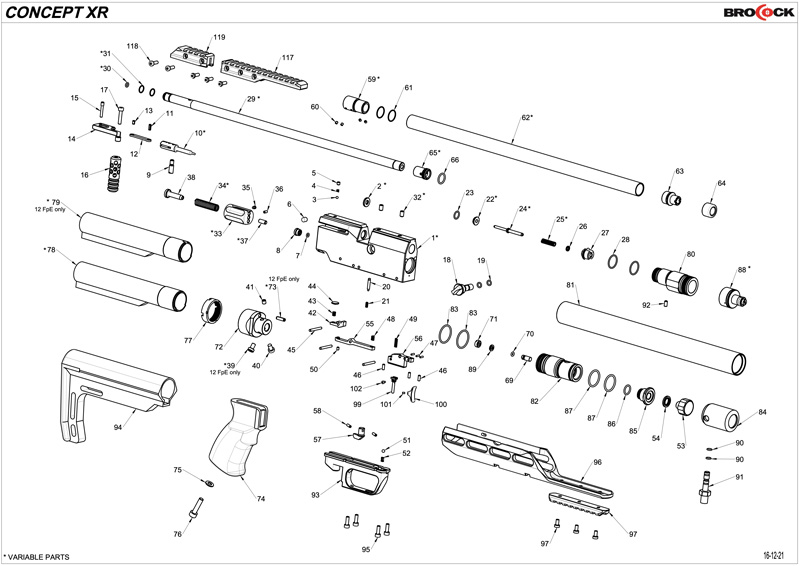
O-Ring Sizes: Compatto XR/Compatto Sniper XR/Concept XR
| PART NO. | DESCRIPTION | CODE | QTY |
|---|---|---|---|
| 19 | o-ring - Ø5x1.5 - NBR - 70Sh | D3OR05X15CO | 2 |
| 22 | valve seal Ø4.5 BRK (12 ft/lbs ) | BCVASE45 | 1 |
| 22 | valve seal Ø5.1 BRK ( 0,22 - FAC ) | BCVASE51 | 1 |
| 22 | valve seal Ø5.8 BRK ( 0,25 - FAC ) | BCVASE58 | 1 |
| 23 | o-ring Ø9x1.5 - NBR - 70Sh | BC0R9X15N70 | 1 |
| 28 | o-ring Ø17x1.5 - NBR - 70Sh | OR17X1.5N70 | 2 |
| 30 | o-ring Ø4x1.5 - NBR - 70Sh ( cal. 0,177 ) | D3OR04X15CO | 1 |
| 30 | o-ring Ø5x1.5 - NBR - 70Sh ( cal. 0,22 ) | D3OR05X15CO | 1 |
| 30 | o-ring Ø6x1.5 - NBR - 70Sh ( cal. 0,25 ) | D3OR06X15CO | 1 |
| 31 | o-ring Ø11x1 - NBR - 70Sh ( Ø13 rod barrel ) | BC0R11X170 | 2 |
| 31 | o-ring Ø9 x1-NBR-70Sh ( Ø11,5 rod barrel ) | BC0R9X170 | 2 |
| 62 | ISM rear plug Compatto ( Ø11,5 rod barrel - LP breech) | BCREPL0 | 1 |
| 62 | ISM rear plug Compatto ( Ø13 rod barrel - HP breech ) | BCREPL5 | 1 |
| 64 | o-ring Ø15x1 - NBR - 70Sh | BCOR15X17 | 2 |
| 82 | o-ring 006 - Ø2.9x1.78 (2012) - urethane | D3ORURA06FV | 1 |
| 90 | o ring 021 ( Ø23.52x1.78 ) -NBR-70Sh | BCR21700 | 2 |
| 90 | o ring 021 ( Ø23.52x1.78 ) -NBR-70Sh | BCR21700 | 4 |
| 93 | o-ring 806 ( Ø11.1x1.78 ) - NBR - 70SH | BCOR80670 | 1 |
| 94 | o ring Ø21x2 - NBR - 70Sh | BCOR21X270 | 2 |
| 97 | o-ring Ø4.5x1.5 - NBR - 70Sh | D3ON7045X15 | 2 |
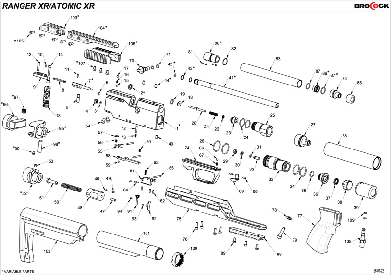
O-Ring Sizes: Atomic/Ranger
| PART NO. | DESCRIPTION | CODE | QTY |
|---|---|---|---|
| 3 | o-ring Ø3x1.5 - NBR - 70Sh | BCOR31570 | 1 |
| 18 | valve seal Ø4.5 BRK (12 ft/lbs ) | BCVASE45 | 1 |
| 18 | valve seal Ø5.1 BRK ( 0,22 - FAC ) | BCVASE51 | 1 |
| 18 | valve seal Ø5.8 BRK ( 0,25 - FAC ) | BCVASE58 | 1 |
| 19 | o-ring Ø9x1.5 - NBR - 70Sh | BC0R9X15N70 | 1 |
| 24 | o-ring Ø17x1.5 - NBR - 70Sh | OR17X1.5N70 | 2 |
| 26 | o ring 021 ( Ø23.52x1.78 ) -NBR-70Sh | BCR21700 | 4 |
| 31 | o-ring 006 - Ø2.9x1.78 (2012) - urethane | D3ORURA06FV | 1 |
| 34 | o ring Ø21x2 - NBR - 70Sh | BCOR21X270 | 2 |
| 35 | o-ring 806 ( Ø11.1x1.78 ) - NBR - 70SH | BCOR80670 | 1 |
| 42 | o-ring Ø4x1.5 - NBR - 70Sh ( cal. 0,177 ) | D3OR04X15CO | 1 |
| 42 | o-ring Ø5x1.5 - NBR - 70Sh ( cal. 0,22 ) | D3OR05X15CO | 1 |
| 42 | o-ring Ø6x1.5 - NBR - 70Sh ( cal. 0,25 ) | D3OR06X15CO | 1 |
| 43 | o-ring Ø9 x1-NBR-70Sh ( Ø11,5 rod barrel ) | BC0R9X170 | 2 |
| 43 | o-ring Ø11x1 - NBR - 70Sh ( Ø13 rod barrel ) | BC0R11X170 | 2 |
| 71 | o-ring - Ø5x1.5 - NBR - 70Sh | D3OR05X15CO | 2 |
| 82 | o-ring Ø15x1 - NBR - 70Sh | BCOR15X17 | 2 |
| 87 | o-ring Ø12 x1.5-NBR-70Sh | D3OR12X15C0 | 2 |
| 87 | o-ring Ø14x1.5 - NBR - 70Sh | OR14X1.5NB70 | 1 |
O-Ring Sizes: XR/Sniper XR
| PART NO. | DESCRIPTION | CODE | QTY |
|---|---|---|---|
| 7 | o-ring Ø3x1.5 - NBR - 70Sh | BCOR31570 | 1 |
| 19 | o-ring - Ø5x1.5 - NBR - 70Sh | D3OR05X15CO | 2 |
| 22 | valve seal Ø4.5 BRK (12 ft/lbs ) | BCVASE45 | 1 |
| 22 | valve seal Ø5.1 BRK ( 0,22 - FAC ) | BCVASE51 | 1 |
| 22 | valve seal Ø5.8 BRK ( 0,25 - FAC ) | BCVASE58 | 1 |
| 23 | o-ring Ø9x1.5 - NBR - 70Sh | BC0R9X15N70 | 1 |
| 28 | o-ring Ø17x1.5 - NBR - 70Sh | OR17X1.5N70 | 2 |
| 30 | o-ring Ø4x1.5 - NBR - 70Sh ( cal. 0,177 ) | D3OR04X15CO | 1 |
| 30 | o-ring Ø5x1.5 - NBR - 70Sh ( cal. 0,22 ) | D3OR05X15CO | 1 |
| 30 | o-ring Ø6x1.5 - NBR - 70Sh ( cal. 0,25 ) | D3OR06X15CO | 1 |
| 31 | o-ring Ø11x1 - NBR - 70Sh ( Ø13 rod barrel ) | BC0R11X170 | 2 |
| 31 | o-ring Ø9 x1-NBR-70Sh ( Ø11,5 rod barrel ) | BC0R9X170 | 2 |
| 64 | o-ring 020 ( Ø21.95x1.78) - NBR - 70Sh | BCOR020N70 | 2 |
| 69 | o ring 019 ( Ø20.35x1.78 ) -NBR-70Sh | OR019N70 | 1 |
| 71 | o-ring 006 - Ø2.9x1.78 (2012) - urethane | D3ORURA06FV | 1 |
| 79 | o ring 617 ( Ø17.86x2.62 ) -NBR - 70Sh | D3OR70617MV | 1 |
Further Videos
XR Assembly: https://youtu.be/G7b1jMIxsNQ?si=yiUdd4uS2qPcnIu1
XR regulator cylinder models: https://youtu.be/tIUoP4oMS-g?si=2sXTcabP-A4WUM6L#
XR regulator bottle models: https://youtu.be/ep19ojWAYno?si=wNJKAtB8jfmFUe2H
01:16 Removing the Stock
01:20 Use a 5mm allen key to remove the stock bolt located at the base of the pistol grip.
01:40 The stock on the Atomic XR and Ranger XR, the stock is removed by undoing four allen bolts surrounding the trigger guard using a 2.5mm allen key. 01:54 The stock on the Commander XR is removed by undoing the stock bolt (5mm allen key) that is revealed by opening a cap on the bottom of the pistol grip.
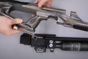
02:20 Pull back the cocking handle and remove the magazine/single shot tray. Dry fire the rifle into a safe direction to conform the rifle is unloaded.
02:32 Degassing the Rifle
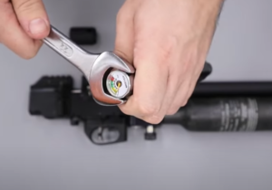
02:37 Make a note of the air pressure as indicated on the regulator pressure as you will want to ensure the regulator is set at the same level when you reassemble the rifle.
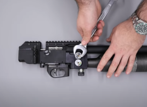
02:53 Use a 22mm spanner to crack the regulator pressure gauge. This will enable air to leak out of the rifle. You will hear the air hiss as it escapes.
03:07 When the hissing has stopped, check the pressure gauges to ensure they read zero pressure.
03:11 Dry fire the rifle a few times to ensure all residual air has been released.
03:18 Full remove the two gauges using a 22mm spanner. Make sure you do not lose the doughty washers underneath the gauges.
03:35 The degassing process for XR rifles fitted with a cylinder and is achieved by pulling off the cap at the front of the cylinder to fully reveal the pressure gauge then crack the gauge loose using a 22mm spanner. Once the air has leaked out, dry fire the rifle to ensure there is no residual air.
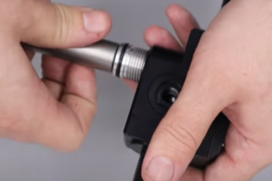
04:00 Unscrew and remove the air bottle. Remove the seal from the thread that has been exposed.
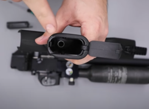
04:24 The two halves of the Picatinny scope rail are removed by loosening the five allen screws with a 3mm allen key.
04:34 Removing the Barrel and Shroud Assembly
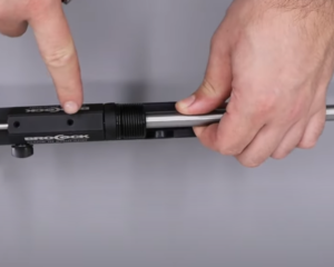
04:37 The shroud is removed by unscrewing it from the barrel.
04:52 The barrel is removed from the block by undoing the two grub screws located on the top of the action forward of the breech using a 2.5mm allen key.
05:30 The back carrier for the shroud is removed from the barrel by loosening the two grub screws using a 2.5mm allen key.
05:42 The shroud carrier at the front of the barrel can be removed using a set of snap ring pliers to purchase two of the holes and then unscrewing. Note: the carrier is secured with blue Loctite.
06:05 Removing the Trigger guard and Safety
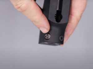
06:08 The trigger plate and trigger guard are removed by removing the four screws at the base of the trigger guard using a 2.5mm allen key. (06:19) Be aware that under the screw that is directly below the power adjuster there is a small spring and plunger.
06:35 With the spring and plunger removed, pull the power adjuster dial off the block.
07:08 The trigger housing can be disassembled further by removing the screws at the front and back using a 3mm allen key.

CAUTION
07:19 The safety catch is removed by removing the two grub screws – one on the side and one on the top.
07:28 Remove the top screw using a 1.5mm allen key. Take care to not lose a small ball bearing and spring underneath. (07:46) remove the screw on the side using a 1.5mm allen key. This will allow the safety catch to be fully removed.
08:00 Removing the Regulator Housing/Cylinder
08:02 The front bottle connection is removed by loosening the two grub screws in the front of the block at the base of the breech using a 2.5mm allen key. With the grub screws loose you will be able rotate and undo the front block from the main block.
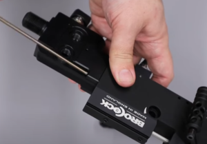
Note that on XR models fitted with an air cylinder. (08:35) Unscrew the cylinder from the back housing. The housing is held captive in the rifle and released with a small locking grub screw that you will need to remove.

09:20 The valve return spring is removed from the block using a pair of tweezers. The valve can then be removed using tweezers also.
09:30 The valve seat and peak valve can then be removed using a BRK Brocock valve removal tool.
10:48 Disassembling the Regulator Housing
11:08 Remove the back cap for the valve return spring using a set of snap ring pliers
11:20 Remove the foster fitting cap and then the fill valve itself using a pair of snap rings pliers.
11:38 Separate the two halves of the foster fit valve you will need to grip the back section in a vice then use snap ring pliers to undo the top section.
11:58 To separate the one way valve from the foster fit housing you will need to connect the foster fit to a dive bottle and carefully and briefly apply a small amount of low air pressure. Place the valve on a firm surface so it does not fly out dangerously. This will force the one way valve out.
13:13 To remove the regulator you will need to use a BRK/Daystate specific tool on the back of the regulator and then unscrewing it. If you do not have a removal tool you will be able to use a set of snap ring pliers.
13:33 Disassembling the Bottle Regulator
16:11 Disassembling the Cylinder (XR models fitted with an air cylinder instead of a bottle)
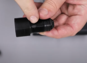
16:47 Pull the plastic collar off the front of the cylinder to fully reveal the pressure gauge. This will enable you to remove the gauge with a 22mm spanner.
17:05 Remove the end cap by unscrewing it from the cylinder.
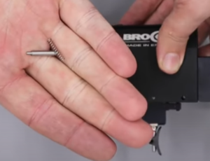
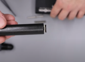
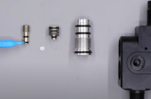
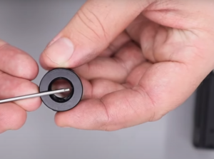
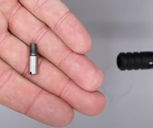
17:28 The regulator at the back of the cylinder can be removed by using an M3 bolt to screw into the back of the regulator lightly to provide purchase and then gently pulling it free.
17:48 The filter for the one way valve in the filler housing can be removed with a large flat bladed screwdriver. (18:16) With that removed, the one way valve can be removed by inserting the air filler probe and delivering a momentary low pressure spurt of air. Place the filler housing on a flat surface to ensure the valve does not fly out and get lost or cause injury.
18:30 Disassembly of the Cylinder Regulator (XR models fitted with an air cylinder instead of a bottle)
18:36 Using a set of digital callipers, measure the extent to which the brass regulator adjustment screw protrudes from the regulator housing. This will be necessary to ensure you reset the regulator pressure correctly when reassembling the regulator.
19:00 Remove the regulator adjustment screw using a flat bladed screwdriver.
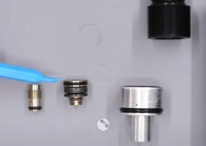
19:16 Use a set of snap ring pliers to remove the snap ring in the base of the regulator.
19:23 Use an M3 bolt to screw lightly into the piston and then pull the piston out. Ensure the white sealing disc does not get lost.
20:54 Removing Trigger and Trigger Sears
Note that the hammer spring adjuster is incorporated into the stock on rifles fitted with an AR15 style adjustable stock. (21:16) To remove it, the stock must first be removed by loosening a ring nut either with a purpose made tool or by tapping it gently with a punch. (21:26) The butt can then be unscrewed from the hammer spring adjuster. (21:28) The hammer spring adjuster is attached to the main block on rifles not fitted with an AR15 style stock.
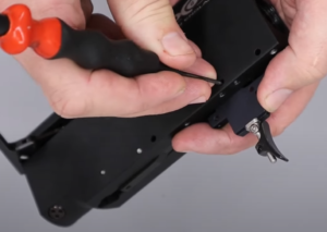
21:57 Use a 2mm punch to remove the three pins in the side of the block. Take care to not lose the springs behind the sear.
22:55 Removing the Hammer Assembly
22:57 The hammer spring adjust is removed by removing the two bolts at the rear of the block. On 12 ft/lbs rifles, one of the screws is an anti-tamper screw and is best removed with the Daystate/BRK anti tamper tool. The other screw is removed with a 3mm allen key.
23:34 With the two bolts removed, the hammer spring adjuster and hammer spring will tip out of the rear of the rifle.
23:40 The hammer spring adjuster can be further disassembled. (23:44) An allen bolt can be removed using a 2.5mm allen key to release the hammer spring adjuster from the back.
23:57 Sub 12 ft/lbs rifles, a pin prevents access to the hammer spring adjuster and can be removed using a set of pliers.
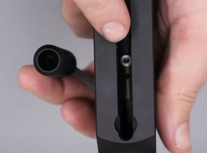
24:19 To remove the hammer from the rear of the rifle, use a small flat head screwdriver, undo the screw visible in a slot on the left side of the block. This will allow the hammer to slide out of the back of the block.
24:57 The cocking dog can be removed from the underside of the block by undoing the screw with a flat head screwdriver inserted through a slot in the bottom of the block.
25:18 Removing Cocking Arm and Pellet Probe
25:23 Remove the second small grub screw from the back on top of the block using a 2mm allen key. This will allow a small spring and ball bearing to be tapped out. If it does not fall out easily, you can use a magnet.
25:48 Remove the pivot point screw at the back of the top of the block using 2mm allen key. This will allow the cocking arm and pellet probe to be removed from the back of the rifle.