BRK BROCOCK XR SERIES
Reassembly Guide (all XR models)
On this Page
- Tools you will need
- Installing the cocking arm and pellet probe
- Installing the hammer assembly
- Installing the trigger and trigger sears
- Assembling the regulator (BRK/Brocock air bottle rifles)
- Assembling the regulator housing (BRK/Brocock air bottle rifles)
- Assembling the regulator (BRK/Brocock air cylinder rifles)
- Assembling the cylinder (BRK/Brocock air cylinder rifles)
- Installing the firing valve
- Installing the regulator housing (BRK/Brocock air bottle rifles)
- Installing the cylinder to the block (BRK/Brocock air cylinder rifles)
- Assembling the trigger and safety
- Assembling the trigger guard, power adjuster and safety
- Installing the barrel and shroud
- Adjusting the regulator
- Adjusting the power
- Installing the stock
Introduction
BRK Brocock air rifles are engineered to the highest standards, but like anything else, they require repairs and servicing work to be carried out both in and out of warranty.
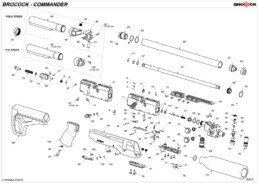
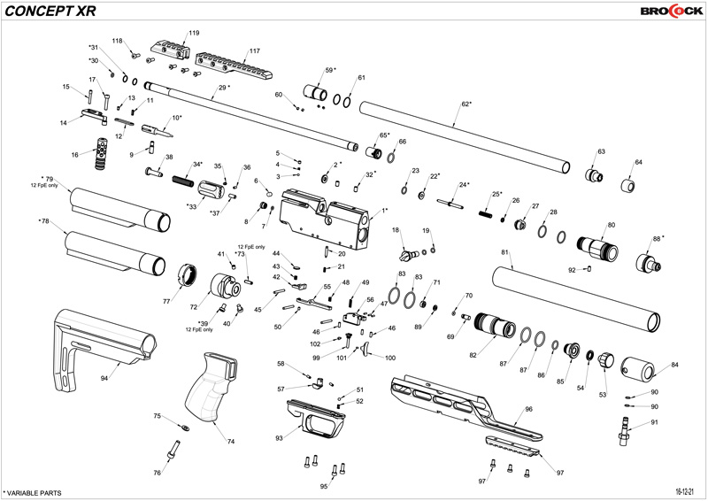
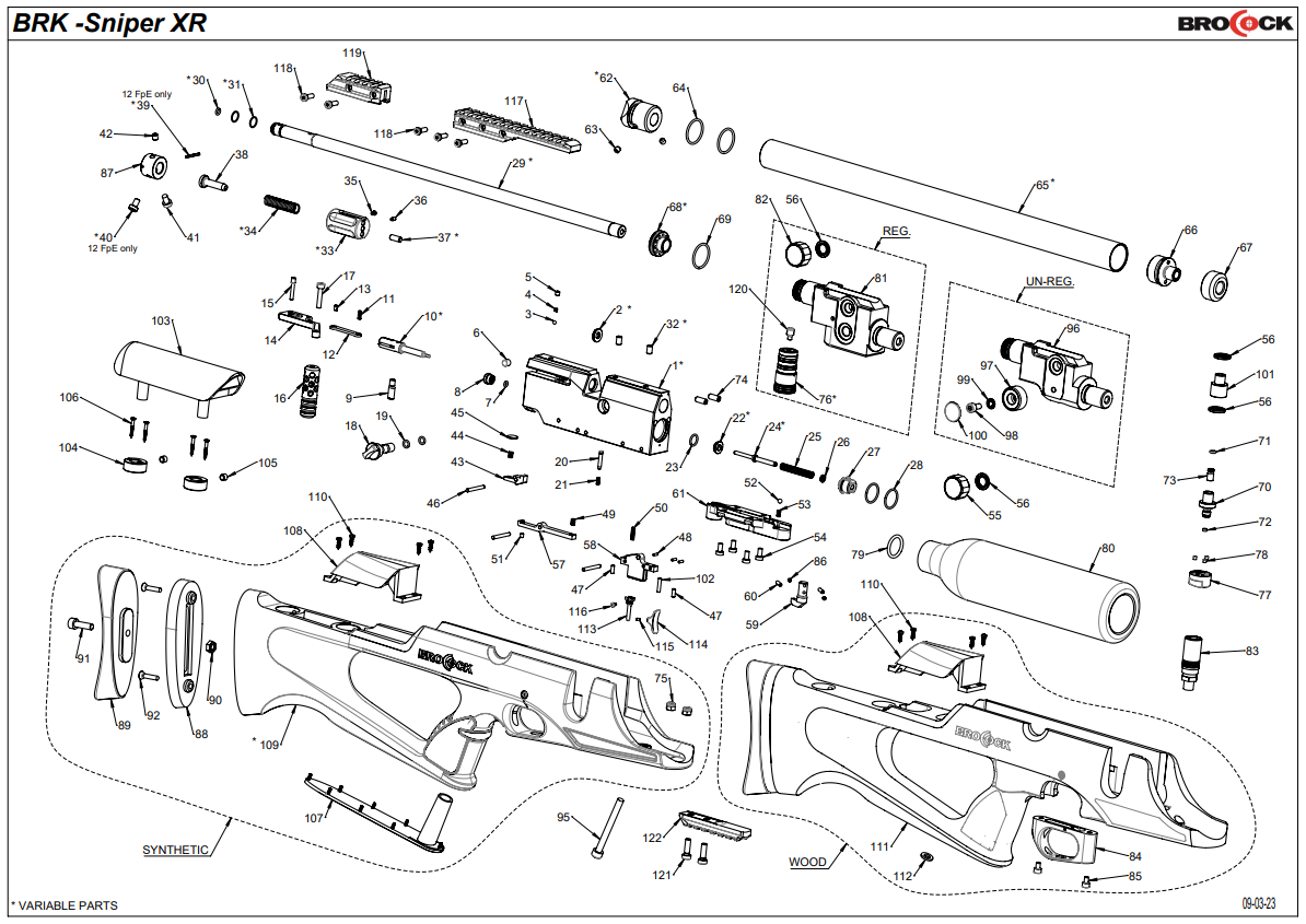
The aim of this guide and the accompanying videos are to help you undertake work on the BRK Brocock XR series of rifles. Although the rifle in this video is the BRK Sniper XR, the information is relevant to all XR series rifle. Only the stock, barrel length and air bottle options differ. Where components on the Ranger XR, Atomic XR, Commander XR and Concept XR differ, these differences will be explained.
Compressed air is dangerous. You should only use this guide if you are a qualified and experienced gunsmith used to working with compressed air. Before you carry out any work on a BRK XR, or any PCP air rifle for that matter, you must ensure it is not cocked, not loaded and empty of air.
Tools You Will Need
- Allen keys: 0.89, 1.5, 2, 2.5, 3, 4 and 5mm
- Long nose pliers
- Open ended 22mm spanner
- 8mm spanner
- 3 pin anti-tamper tool
- Regulator removal tool
- Tweezers
- Snap ring pliers
- Flat bladed screwdrivers: 3, 6 and 10mm
- Magnet
O-Ring Sizes: Ghost
| PART NO. | DESCRIPTION | CODE | QTY |
|---|---|---|---|
| 3 | o ring Ø13x1.5 - NBR 70Sh | D3OR13X1.5N70 | 2 |
| 4 | o-ring Ø14.5x3 - NBR - 90Sh | OR14.5X3N90 | 1 |
| 7 | o-ring Ø4x1.5 - NBR - 70Sh | D3OR04X15CO | 1 |
| 14 | o-ring 006 - Ø2.9x1.78 (2012) - urethane | D3ORURA06FV | 1 |
| 16 | o ring Ø15x2 - NBR 70Sh | D3OR15X02CO | 3 |
| 19 | o-ring Ø9x1.5 - NBR - 70Sh | BC0R9X15N70 | 1 |
| 20 | o-ring Ø17x1.5 - NBR - 70Sh | OR17X1.5N70 | 1 |
| 23 | o-ring 004 ( Ø1.78x1.78 ) - NBR - 90Sh | D3OR004N90 | 1 |
| 32 | o ring 617 ( Ø17.86x2.62 ) -NBR - 70Sh | D3OR70617MV | 1 |
| 35 | o-ring 007 ( Ø3.68x1.78 ) - NBR - 90SH | OR007N90 | 1 |
| 36 | bonded dowty seal M12 - 867 | BOSEM12867 | 2 |
| 37 | o-ring Ø9.3x2.4 - NBR - 90Sh | OR93X24N90 | 1 |
| 39 | o-ring 006 - Ø2.9x1.78 (2012) - urethane | D3ORURA06FV | 1 |
| 42 | dowty seal self centering 1/8 bsp | D3DOSE18NCO | 3 |
| 130 | o-ring Ø4.1x1.6 - NBR - 70Sh ( cal. 0,177" ) | OR4.1X1.6N70 | 1 |
| 130 | o ring 009 - Ø5.28x1.78 -NBR-70Sh ( cal. 0,22" ) | OR009N70 | 1 |
| 130 | o-ring Ø6.1x1.6 - NBR - 70Sh ( cal. 0,25" ) | OR6.1X1.6N70 | 1 |
| 130 | o-ring Ø7.5x1.5 - NBR - 70Sh ( cal. 0,30" ) | D3OR75X15N70 | 1 |
| 133 | o-ring 813 - NBR - 70Sh | D3OR813N70 | 2 |
O-Ring Sizes: Commander/Pathfinder
| PART NO. | DESCRIPTION | CODE | QTY |
|---|---|---|---|
| 7 | o-ring Ø3x1.5 - NBR - 70Sh | BCOR31570 | 1 |
| 19 | o-ring - Ø5x1.5 - NBR - 70Sh | D3OR05X15CO | 2 |
| 22 | valve seal Ø4.5 BRK (12 ft/lbs ) | BCVASE45 | 1 |
| 22 | valve seal Ø5.1 BRK ( 0,22 - FAC ) | BCVASE51 | 1 |
| 22 | valve seal Ø5.8 BRK ( 0,25 - FAC ) | BCVASE58 | 1 |
| 23 | o-ring Ø9x1.5 - NBR - 70Sh | BC0R9X15N70 | 1 |
| 28 | o-ring Ø17x1.5 - NBR - 70Sh | OR17X1.5N70 | 2 |
| 30 | o-ring Ø4x1.5 - NBR - 70Sh ( cal. 0,177 ) | D3OR04X15CO | 1 |
| 30 | o-ring Ø5x1.5 - NBR - 70Sh ( cal. 0,22 ) | D3OR05X15CO | 1 |
| 30 | o-ring Ø6x1.5 - NBR - 70Sh ( cal. 0,25 ) | D3OR06X15CO | 1 |
| 31 | o-ring Ø11x1 - NBR - 70Sh ( Ø13 rod barrel ) | BC0R11X170 | 2 |
| 31 | o-ring Ø9 x1-NBR-70Sh ( Ø11,5 rod barrel ) | BC0R9X170 | 2 |
| 64 | o-ring 020 ( Ø21.95x1.78) - NBR - 70Sh | BCOR020N70 | 2 |
| 69 | o ring 019 ( Ø20.35x1.78 ) -NBR-70Sh | OR019N70 | 1 |
| 71 | o-ring 006 - Ø2.9x1.78 (2012) - urethane | D3ORURA06FV | 1 |
| 79 | o ring 617 ( Ø17.86x2.62 ) -NBR - 70Sh | D3OR70617MV | 1 |
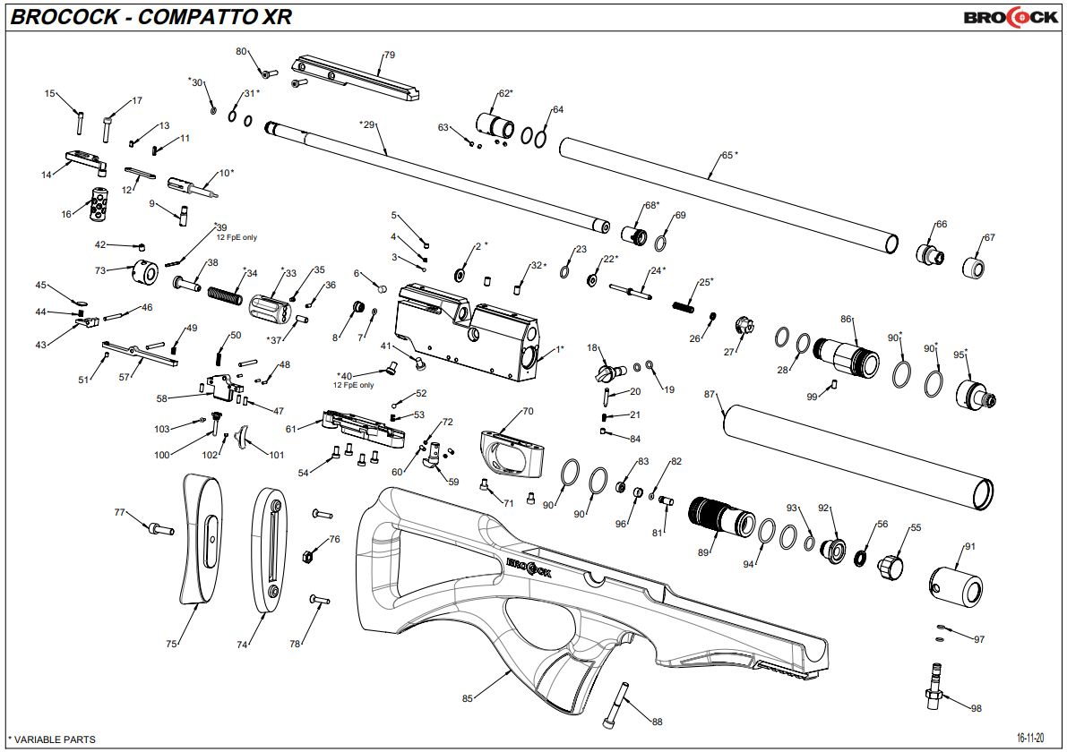
O-Ring Sizes: Compatto XR/Compatto Sniper XR/Concept XR
| PART NO. | DESCRIPTION | CODE | QTY |
|---|---|---|---|
| 19 | o-ring - Ø5x1.5 - NBR - 70Sh | D3OR05X15CO | 2 |
| 22 | valve seal Ø4.5 BRK (12 ft/lbs ) | BCVASE45 | 1 |
| 22 | valve seal Ø5.1 BRK ( 0,22 - FAC ) | BCVASE51 | 1 |
| 22 | valve seal Ø5.8 BRK ( 0,25 - FAC ) | BCVASE58 | 1 |
| 23 | o-ring Ø9x1.5 - NBR - 70Sh | BC0R9X15N70 | 1 |
| 28 | o-ring Ø17x1.5 - NBR - 70Sh | OR17X1.5N70 | 2 |
| 30 | o-ring Ø4x1.5 - NBR - 70Sh ( cal. 0,177 ) | D3OR04X15CO | 1 |
| 30 | o-ring Ø5x1.5 - NBR - 70Sh ( cal. 0,22 ) | D3OR05X15CO | 1 |
| 30 | o-ring Ø6x1.5 - NBR - 70Sh ( cal. 0,25 ) | D3OR06X15CO | 1 |
| 31 | o-ring Ø11x1 - NBR - 70Sh ( Ø13 rod barrel ) | BC0R11X170 | 2 |
| 31 | o-ring Ø9 x1-NBR-70Sh ( Ø11,5 rod barrel ) | BC0R9X170 | 2 |
| 62 | ISM rear plug Compatto ( Ø11,5 rod barrel - LP breech) | BCREPL0 | 1 |
| 62 | ISM rear plug Compatto ( Ø13 rod barrel - HP breech ) | BCREPL5 | 1 |
| 64 | o-ring Ø15x1 - NBR - 70Sh | BCOR15X17 | 2 |
| 82 | o-ring 006 - Ø2.9x1.78 (2012) - urethane | D3ORURA06FV | 1 |
| 90 | o ring 021 ( Ø23.52x1.78 ) -NBR-70Sh | BCR21700 | 2 |
| 90 | o ring 021 ( Ø23.52x1.78 ) -NBR-70Sh | BCR21700 | 4 |
| 93 | o-ring 806 ( Ø11.1x1.78 ) - NBR - 70SH | BCOR80670 | 1 |
| 94 | o ring Ø21x2 - NBR - 70Sh | BCOR21X270 | 2 |
| 97 | o-ring Ø4.5x1.5 - NBR - 70Sh | D3ON7045X15 | 2 |
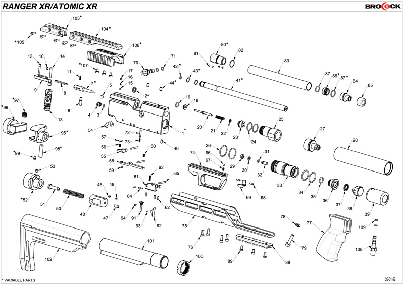
O-Ring Sizes: Atomic/Ranger
| PART NO. | DESCRIPTION | CODE | QTY |
|---|---|---|---|
| 3 | o-ring Ø3x1.5 - NBR - 70Sh | BCOR31570 | 1 |
| 18 | valve seal Ø4.5 BRK (12 ft/lbs ) | BCVASE45 | 1 |
| 18 | valve seal Ø5.1 BRK ( 0,22 - FAC ) | BCVASE51 | 1 |
| 18 | valve seal Ø5.8 BRK ( 0,25 - FAC ) | BCVASE58 | 1 |
| 19 | o-ring Ø9x1.5 - NBR - 70Sh | BC0R9X15N70 | 1 |
| 24 | o-ring Ø17x1.5 - NBR - 70Sh | OR17X1.5N70 | 2 |
| 26 | o ring 021 ( Ø23.52x1.78 ) -NBR-70Sh | BCR21700 | 4 |
| 31 | o-ring 006 - Ø2.9x1.78 (2012) - urethane | D3ORURA06FV | 1 |
| 34 | o ring Ø21x2 - NBR - 70Sh | BCOR21X270 | 2 |
| 35 | o-ring 806 ( Ø11.1x1.78 ) - NBR - 70SH | BCOR80670 | 1 |
| 42 | o-ring Ø4x1.5 - NBR - 70Sh ( cal. 0,177 ) | D3OR04X15CO | 1 |
| 42 | o-ring Ø5x1.5 - NBR - 70Sh ( cal. 0,22 ) | D3OR05X15CO | 1 |
| 42 | o-ring Ø6x1.5 - NBR - 70Sh ( cal. 0,25 ) | D3OR06X15CO | 1 |
| 43 | o-ring Ø9 x1-NBR-70Sh ( Ø11,5 rod barrel ) | BC0R9X170 | 2 |
| 43 | o-ring Ø11x1 - NBR - 70Sh ( Ø13 rod barrel ) | BC0R11X170 | 2 |
| 71 | o-ring - Ø5x1.5 - NBR - 70Sh | D3OR05X15CO | 2 |
| 82 | o-ring Ø15x1 - NBR - 70Sh | BCOR15X17 | 2 |
| 87 | o-ring Ø12 x1.5-NBR-70Sh | D3OR12X15C0 | 2 |
| 87 | o-ring Ø14x1.5 - NBR - 70Sh | OR14X1.5NB70 | 1 |
O-Ring Sizes: XR/Sniper XR
| PART NO. | DESCRIPTION | CODE | QTY |
|---|---|---|---|
| 7 | o-ring Ø3x1.5 - NBR - 70Sh | BCOR31570 | 1 |
| 19 | o-ring - Ø5x1.5 - NBR - 70Sh | D3OR05X15CO | 2 |
| 22 | valve seal Ø4.5 BRK (12 ft/lbs ) | BCVASE45 | 1 |
| 22 | valve seal Ø5.1 BRK ( 0,22 - FAC ) | BCVASE51 | 1 |
| 22 | valve seal Ø5.8 BRK ( 0,25 - FAC ) | BCVASE58 | 1 |
| 23 | o-ring Ø9x1.5 - NBR - 70Sh | BC0R9X15N70 | 1 |
| 28 | o-ring Ø17x1.5 - NBR - 70Sh | OR17X1.5N70 | 2 |
| 30 | o-ring Ø4x1.5 - NBR - 70Sh ( cal. 0,177 ) | D3OR04X15CO | 1 |
| 30 | o-ring Ø5x1.5 - NBR - 70Sh ( cal. 0,22 ) | D3OR05X15CO | 1 |
| 30 | o-ring Ø6x1.5 - NBR - 70Sh ( cal. 0,25 ) | D3OR06X15CO | 1 |
| 31 | o-ring Ø11x1 - NBR - 70Sh ( Ø13 rod barrel ) | BC0R11X170 | 2 |
| 31 | o-ring Ø9 x1-NBR-70Sh ( Ø11,5 rod barrel ) | BC0R9X170 | 2 |
| 64 | o-ring 020 ( Ø21.95x1.78) - NBR - 70Sh | BCOR020N70 | 2 |
| 69 | o ring 019 ( Ø20.35x1.78 ) -NBR-70Sh | OR019N70 | 1 |
| 71 | o-ring 006 - Ø2.9x1.78 (2012) - urethane | D3ORURA06FV | 1 |
| 79 | o ring 617 ( Ø17.86x2.62 ) -NBR - 70Sh | D3OR70617MV | 1 |
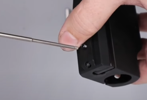
Installing the Cocking Arm and Pellet Probe
01:59 Add a small amount of moly or lithium grease to the pellet probe and pivot points on the cocking arm.
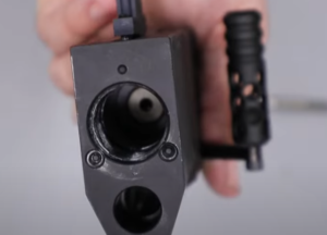
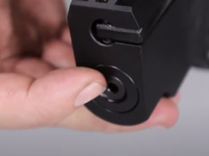
02:24 Insert the pellet probe into the top hole on the back of the main block.
02:28 Align the rear pivot point on the cocking arm with the rearmost hole on top of the block then (02:34) insert the pivot point pin. Tighten with a 2mm allen key.
02:52 Add a small amount of moly grease to the ball bearing and drop it into the second hole from the back of the top of the block. (03:06) Drop the spring on top of the ball bearing then screen in the grub screw (03:11) using a 2mm allen key.
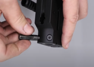
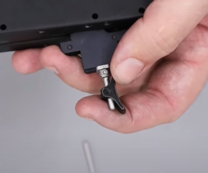
03:27 Apply a small amount of Blue Loctite to the thread to the cocking pin (dog). (03:43) Pull back the cocking handle and insert the cocking pin through the rear of the block, locating it in the hole in the pellet probe. Use a flat bladed screwdriver or similar to position correctly then tighten.
Installing the Hammer Assembly
04:25 Insert the hammer into the rear of the block with the hole that is not located in the recess facing the rear of block. (04:29) Align the hammer so that the recess is aligned with a slot in the side of the block.
04:35 Insert the cheese headed screw through the slot and into the rear hole of the hammer to secure it in place. Tighten with a flat bladed screwdriver.
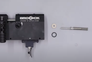
04:53 Adjust the locking screw on the hammer spring adjuster body so it is flush with the body of the adjuster.
05:05 Locate the hole at the very back of the adjuster body. (05:12) Insert the hammer spring adjuster through the back of the adjuster body and screw it home.
05:19 Place the hammer spring over the end of the hammer spring adjuster.
05:26 Locate the bottom of the adjuster body which is denoted by two screw holes and insert the hammer spring adjuster body, hammer spring adjuster and hammer spring into the rear of the block, aligning the two screw holes in the adjuster body with the two holes in the bottom of the block.
05:35 Insert the two securing screws, one of which will be fitted with a three-pin anti-tamper head on 12 ft/lbs models. Tighten the screws with a 3 mm allen key and three pin anti-tamper tool.
Installing the Trigger and Trigger Sears
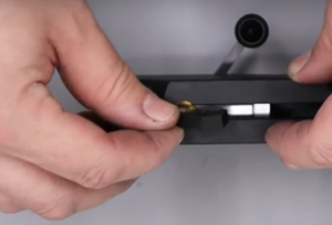
06:12 Working with the block position upside down, use a pair of tweezers to insert the small brass cover to the underside of the pellet probe at the rear of the slot. It simply drops into place.
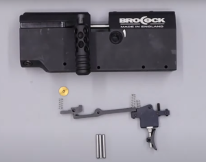
06:15 Add the spring to the back of the rear sear – a small amount of grease applied to the sear will help hold the spring in place. (06:26) Insert the sear into the rear of the slot, aligning the spring with the brass cover.
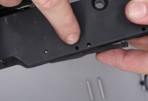
06:30 Holding the sear temporarily in place with your finger, rotate the block and locate the lower hole in the side of the block next to the bottom of the cocking handle. Align the hole with the hole in the sear and insert one of the trigger pins.
06:50 The second, longer sear is inserted slot forward of the first sear with the spring end forward-most. (06:58) The spring hooks into a counter bore inside the block. Hold in place with your finger and insert a trigger pin in the hole in the side of the block next to the hole in which the first pin was inserted.
07:24 The trigger assembly is inserted at the front underside of the block. Locate the hole in the trigger assembly with the second hole from the front of the block. (07:35) Secure with the last trigger pin.
Assembling the Regulator (BRK/Brocock Air Bottle Rifles)
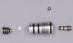
08:39 Add a small amount of moly grease to the piston ‘o’ rings.
08:50 Insert the piston into the rear of the regulator.
08:56 Drop the white sealing disc into the other end of the regulator. Note that if the disc has a dimple on both sides, it should be replaced. If there is a dimple on one side and the other side is flat, insert the disco so the dimple faces the piston.
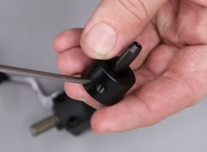
09:26 Add a small amount of moly grease to the ‘o’ rings on the regulator adjuster screw then screw into the top of the regulator using a flat bladed screwdriver. Screw in until you feel the adjuster screw touch the top of the piston then back out a couple of turns.
10:18 Insert the safety screw in the hole at the top of the regulator using a 2mm allen key.
Assembling the Regulator Housing (BRK/Brocock Air Bottle Rifles)
10:32 Screw the back cap for the valve return spring into the upper threaded end of the housing. Tighten with a pair of snap ring pliers.
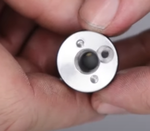
10:48 Apply a small amount of silicon grease to the regulator ‘o’ rings, then drop into the larger of the two holes in the underside of the regulator housing with the adjuster screw end uppermost in the hole. Screw the regulator into place using the regulator tool or a set of snap ring pliers.
11:20 Apply a light amount of silicon grease to the ‘o’ ring on the one-way valve and drop into the foster fitting with the ‘o’ ring uppermost. Screw in the back cap. You will need to hold the larger part of the unit in a soft jaw vice and tighten the other end using a pair of snap ring pliers.
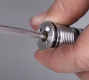
11:54 The foster fitting is inserted in the remaining hole on the underside of the regulator housing and tightened with a set of snap ring pliers.
12:09 Attach the magnetic dust cap.
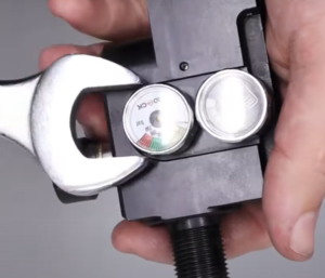
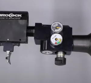
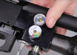
12:21 The bottle pressure gauge is inserted into the lower of the two holes on the side of the regulator housing. The regulator gauge (marked ‘HUMA’) is fitted to the upper hole. Make sure the doughty washers are fitted to the back of the gauges. Use a 22mm spanner to tighten.
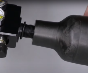
12:50 Apply a small amount of silicon grease to the large ‘o’ ring and slide over the remaining threaded end then screw on the air bottle by hand.
Assembling the Regulator (BRK/Brocock Air Cylinder Rifles)
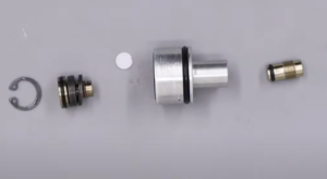
14:08 Add a small amount of silicon grease to the belleville washer stack and ‘o’ rings on the piston.
14:17 Insert the piston int the large open end of the regulator body.
14:25 Add the snap ring on top of the piston to hold it in place. Ensure it is properly seated in the retaining groove.
14:44 Add the white sealing disc. Note that if the disc has a dimple on both sides, it should be replaced. If there is a dimple on one side and the other side is flat, insert the disco so the dimple faces the piston.
15:25 Add a small amount of silicon grease to the ‘o’ ring on the adjuster screw before screwing into the body using a flat headed screwdriver.
15:45 Use a set of callipers to reset the regulator adjustment screw to the measure you took when disassembling. This will ensure the same/similar power setting.
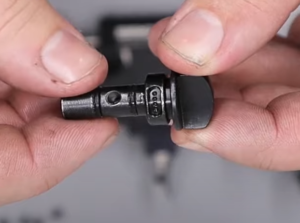
Assembling the Cylinder (BRK/Brocock Air Cylinder Rifles)
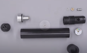
16:23 Add a small amount of silicon grease to the ‘o’ ring on the way valve. Drop into the fill end housing with the ‘o’ ring uppermost and push home with and allen key to ensure it is properly seated.
16:43 Add the washer and finally place the brass filter on top before tightening with a flat head screwdriver. You do not need to over-tighten. The head simply needs to be flush with the hole.
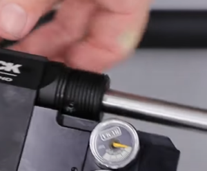
17:13 Screw the cylinder pressure gauge into the fill end housing, making sure the doughty washer is in place. Tighten with a 22mm spanner.
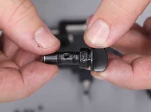
17:30 Add a small amount of silicon grease to the four ‘o’ rings on the filler housing.
17:45 Fit the cylinder cap over the filler gauge end of the cylinder.
17:51 Screw the filler housing into the front (counter bored end) of the air cylinder. (18:27) check that the housing is screwed in far enough by aligning the fill port in the cylinder with the hole in the cylinder cap.
screw in valve assembly until the cap aligns
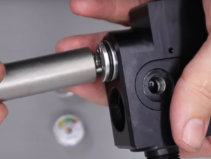
18:46 Add a small amount of silicon grease to the ‘o’ ring on the outside of the regulator as well as the ‘o’ ring seated in the bottom of the regulator. 18:57 Push the regulator into the cylinder to the bottom of the thread. (19:12) Note that screwing in the end cap will push the regulator into position. However, this component must first be inserted into the main block.
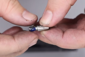
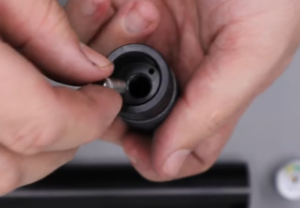
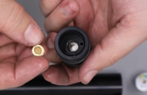
Installing the Firing Valve
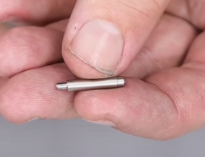
19:31 Apply a small amount of silicon grease to the ‘o’ ring before locating around the valve seat.
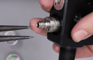
19:42 Using the valve removal tool, place the valve seat over the end with the ‘o’ ring end of the seat facing outermost. Push the valve seat into position through the largest of the two holes at the front of the main block.
20:04 Take the valve pin and use a set of tweezers to push it into position in the valve seat. The valve return spring can then be located over the pin.

Installing the Regulator Housing (BRK/Brocock Air Bottle Rifles)
20:32 Add a small amount of silicon grease to the two ‘o’ rings on the threaded component of the regulator housing.
20:40 Ensure the two grub screws located at the top of the regulator housing are wound out.
20:53 Screw the regulator housing to the main block.
21:16 Use a 2.5mm allen key to screw in the two grub screws at the top of the regulator housing.
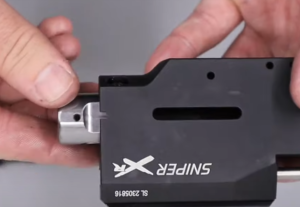
Installing the Cylinder to the Block (BRK/Brocock Air Cylinder Rifles)
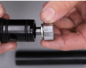
21:36 Apply a small amount of silicon grease to the ‘o’ rings on the smaller threaded end of the connecting component and then screw it into the main block, using an adjustable spanner to tighten.
22:16 Install the small grub screw with a 2mm allen key into the hole on the underside of the block in the slot forward of the trigger.
22:32 Screw the air cylinder into position on the front of the block.
Assembling the Trigger and Safety
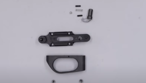
23:17 Take the safety (flag) switch and drop it into the larger of the holes at the front of the trigger plate with the safety (flag) catch pointing back towards the trigger slot.
23:24 Turn the plate over and locate the hole next to the safety (flag) catch. Drop the spring into the hole followed by the ball bearing.
23:36 Use a flat bladed screwdriver to compress the ball bearing and spring. Turn the safety (flag) catch to one side to expose the hole and insert one of the two grub screws using a 1.5mm allen key.
22:48 The second grub screw can be installed in the other side of the flag catch.
25:00 Put the safety catch into the middle and locate the trigger guard on top of the trigger plate. Screw in the two screws using a 3mm allen key.
Assembling the Trigger Guard, Power Adjuster and Safety
Note: cylinder rifles have a captive trigger guard.
25:37 Apply a small amount of silicon grease to the two ‘o’ rings on the power adjuster stem.
25:47 Locate the two slots at the top of the adjuster – one long slot and one short slot. The long slot is used for FAC/high-power rifles, and the short slot is used for 12 ft/lbs rifles.
26:16 Put the power adjuster into the hole on the side of the block ensuing the correct slot for your rifle is orientated towards the bottom of the block. Using the wrong slot is likely to hamper the operation of the transfer port.
26:23 Insert the plunger pin into the small spring with the longer of the two spigot ends first. Insert into the hole in the bottom of the block immediately below the power adjuster.
26:50 Position the trigger guard and safety on the bottom of the block and secure with four allen screws using a 2.5mm allen key. Ensure the trigger guard does not impede movement of the trigger.
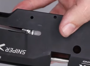
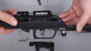
Installing the Barrel and Shroud
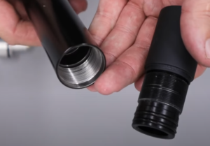
27:42 Put a small amount of silicon grease on the two ‘o’ rings at the back of the barrel.
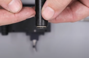
27:50 Align the two dimples in the barrel with the top of the block and push it into the block.
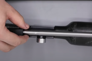
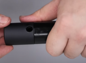
28:09 A small amount of the barrel should protrude into the breech. The two dimples should also be visible through the two holes in the top of the block. If they are you can insert the two grub screws and tighten using a 2.5mm allen key.
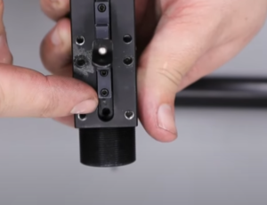
29:03 Locate the shroud back carrier to the back of the barrel ensuring a paper-thin gap between the carrier and the block. Ensure the two flat sides are aligned with the block. Insert the two grub screws and tighten with a 2.5mm allen key.
29:55 Apply a small amount to the ‘o’ ring on the front shroud carrier. Add a small amount of Loctite Blue to the thread on the end of the barrel. Screw on the front shroud carrier with the larger end at the muzzle. Tighten with a pair of snap ring pliers.
30:24 The shroud can then slide over the barrel and screw into the back shroud carrier.
Adjusting the Regulator
Note: regulator pressure can be increased whilst the rifle is under pressure. However, the decrease the regulator pressure the rifle must be de-pressurised. Failure to do this will lead to the regulator being damaged.
It is recommended that the result of any regulator adjustment should be verified using a chronograph to ensure compliance with local law.
31:04 With the rifle pressurised, check the reading on the regulator gauge.
| TYPE | CALIBRE | ENERGY (FT/LBS) | REG PRESS IN BAR |
|---|---|---|---|
| PATHFINDER | 177 | 12 | 120 |
| PATHFINDER | 22 | 12 | 110 |
| PATHFINDER | 177 | 18 | 125 |
| PATHFINDER | 22 | 28 | 130 |
| PATHFINDER | 25 | 28 | 130 |
| RANGER/ATOMIC | 177 | 12 | 130 |
| RANGER/ATOMIC | 22 | 12 | 120 |
| RANGER/ATOMIC | 177 | 18 | 140 |
| RANGER/ATOMIC | 22 | 18 | 130 |
| RANGER/ATOMIC | 25 | 18 | 130 |
| COMMANDER | 177 | 12 | 100 |
| COMMANDER | 22 | 12 | 90 |
| COMMANDER | 22 | 46 | 150 |
| COMMANDER | 22 | 30 | 130 |
| COMMANDER | 177 | 18 | 125 |
| COMMANDER | 25 | 55 | 150 |
| CONCEPT | 177 | 12 | 100 |
| CONCEPT | 22 | 12 | 90 |
| CONCEPT | 22 | 46 | 150 |
| CONCEPT | 22 | 30 | 130 |
| CONCEPT | 177 | 18 | 125 |
| CONCEPT | 25 | 55 | 150 |
Adjusting the Power
Note: in making any adjustments to the power of your rifle, you are responsible for ensuring its compliance with local law. It is recommended that you use a chronograph to correctly assess power output.
32:30 The hammer spring adjuster is located at the back of the main block. To increase power output the hammer spring adjuster must be wound in. To decrease power, it must be wound out.
33:19 Once the desired power setting has been reached, the two bolts at the rear of the block must be removed. One bolt is removed using a 3mm allen key. One 12 ft/lbs rifles the second bolt is fitted with an anti-tamper head, requiring an anti-tamper tool to remove.
33:35 Pull the hammer spring adjuster out of the back of the rifle.
33:42 Tighten the grub screw at the back of the cap using a 2.5mm allen key to lock the hammer spring adjuster into position at the desired power output level.
33:56 Reinstall the hammer spring adjuster at the back of the block and secure with the two allen bolts.
Installing the Stock
34:22 Drop the stock over the action and insert the stock bolt through the bottom of the pistol grip, tightening with a 5mm allen key.