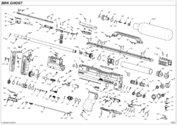
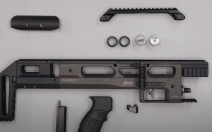
THE BROCOCK GHOST
Reassembly Guide
On this Page
- Tools you will need
- Installing the trigger
- Installing the bottom rail and fill port
- Assembling and installing the firing valve
- Assembling and installing the regulator
- Installing the top rail and cocking linkage
- Assembling and installing the rear block
- Installing the grip, cheek piece, top rail and gauges
- Installing the barrel, shroud and pellet probe
- Gassing up the rifle and adjusting the regulator
Introduction
BRK Brocock air rifles are engineered to the highest standards, but like anything else, they require repairs and servicing work to be carried out both in and out of warranty.
All BRK Brocock PCP air rifles are engineered to the highest standards. However, like anything mechanical, they require servicing and, even, repairs (in and out of warranty). The aim of this guide and the accompanying step-by-step videos is to specifically help you undertake work on the BRK Brocock GHOST Series models.
Important: Compressed air is dangerous! So you should only use this guide if you are an experienced gunsmith and conversant working with compressed airguns. If you do not consider yourself competent, please take your rifle to you local authorised BRK Brocock Service Center or contact the factory for advice.
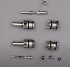
| PART NO. | DESCRIPTION | CODE | QTY |
|---|---|---|---|
| 3 | o ring Ø13x1.5 - NBR 70Sh | D3OR13X1.5N70 | 2 |
| 4 | o-ring Ø14.5x3 - NBR - 90Sh | OR14.5X3N90 | 1 |
| 7 | o-ring Ø4x1.5 - NBR - 70Sh | D3OR04X15CO | 1 |
| 14 | o-ring 006 - Ø2.9x1.78 (2012) - urethane | D3ORURA06FV | 1 |
| 16 | o ring Ø15x2 - NBR 70Sh | D3OR15X02CO | 3 |
| 19 | o-ring Ø9x1.5 - NBR - 70Sh | BC0R9X15N70 | 1 |
| 20 | o-ring Ø17x1.5 - NBR - 70Sh | OR17X1.5N70 | 1 |
| 23 | o-ring 004 ( Ø1.78x1.78 ) - NBR - 90Sh | D3OR004N90 | 1 |
| 32 | o ring 617 ( Ø17.86x2.62 ) -NBR - 70Sh | D3OR70617MV | 1 |
| 35 | o-ring 007 ( Ø3.68x1.78 ) - NBR - 90SH | OR007N90 | 1 |
| 36 | bonded dowty seal M12 - 867 | BOSEM12867 | 2 |
| 37 | o-ring Ø9.3x2.4 - NBR - 90Sh | OR93X24N90 | 1 |
| 39 | o-ring 006 - Ø2.9x1.78 (2012) - urethane | D3ORURA06FV | 1 |
| 42 | dowty seal self centering 1/8 bsp | D3DOSE18NCO | 3 |
| 130 | o-ring Ø4.1x1.6 - NBR - 70Sh ( cal. 0,177" ) | OR4.1X1.6N70 | 1 |
| 130 | o ring 009 - Ø5.28x1.78 -NBR-70Sh ( cal. 0,22" ) | OR009N70 | 1 |
| 130 | o-ring Ø6.1x1.6 - NBR - 70Sh ( cal. 0,25" ) | OR6.1X1.6N70 | 1 |
| 130 | o-ring Ø7.5x1.5 - NBR - 70Sh ( cal. 0,30" ) | D3OR75X15N70 | 1 |
| 133 | o-ring 813 - NBR - 70Sh | D3OR813N70 | 2 |
Tools You Will Need
- 1.5, 2, 2.5, 3 and 4mm allen keys
- Snap ring pliers
- Long nose pliers
- 8mm spanner
- Open ended spanners: 19 and 22mm
- Valve removal tool
- Regulator removal tool
- 3-pin anti-tamper removal tool
- Tweezers
- 6mm flat blade screwdriver
- ‘o’ ring pick
Note: The rifle used in the accompanying video is a 12 ft/lbs Ghost Carbine in .22 calibre. However, the information relates to all models and calibres including high power/FAC models.
Installing the Trigger
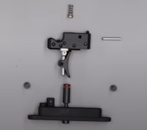
01:15 Insert the trigger linkage into the channel at the bottom of the block, compressing the spring slightly and hooking it over the rear of the block. Slide the plastic cover into the channel (01:26) to cover the trigger linkage.
01:44 Then insert the small spring and brass cup into the hole at the top of the trigger assembly.
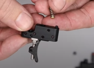
01:52 Now instal the trigger assembly and insert it into the block, aligning the rear most pin hole in the trigger block with the smaller of the two holes visible in the cut out. Then insert the trigger pin (02:05).
02:26 Install the trigger plate and safety into the same cavity. The safety bolt inserts into the larger hole. However, you may need to wiggle the trigger slightly to ensure it is properly located. Secure with two screws (02:40) and tighten with a 2mm allen key.
02:49 You can check the trigger is properly seated by pulling it and making sure the end of the trigger linkage moves.
Trigger Adjustment Full trigger adjustment is covered in the BRK Ghost handbook. A comprehensive trigger adjustment video can be found here
Installing the Bottom Rail and Fill Port
03:08 Take the one-way valve and add a small amount of silicon grease to the ‘o’ ring.
03:14 Insert the one-way valve into the bottom of the foster fit housing with the ‘o’ ring at the bottom.
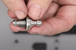
03:25 Ensure the doughty washer is in place on the thread and then screw the valve housing into the bottom of the block using a deep 10mm socket.
03:41 The bottom rail is placed over the trigger and fill valve and secured with three screws that are tightened with a 3mm allen key. Replace the dust cover (04:03).
Assembling and Installing the Firing Valve
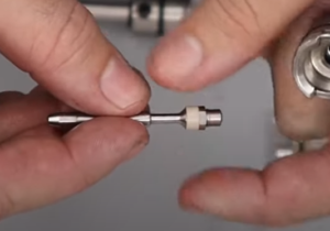
04:22 Apply a small amount of silicon grease to the small ‘o’ ring. Then drop into the back housing, also making sure it is properly seated.
04:37 Drop the back cap into position, long stem first. Push it home gently.
04:47 Add a small amount of silicon grease to the valve pin and push into the front part of the housing long stem first. Then, you can fully push it home.
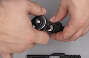
04:57 The valve return spring can then be dropped in over the valve and the two halves of the housing can be joined, aligning the cut outs on the two halves as well as the ring. (05:12) with the two halves and the ring aligned, rotate the ring to lock everything in place.
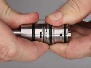
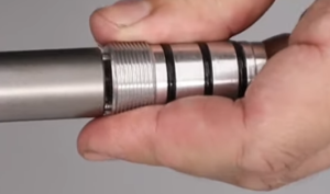
06:03 Apply a light coat of silicon grease to the three ‘o’ rings on the valve body.
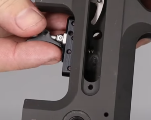
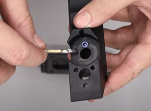
06:17 Insert the valve into the larger hole in the end of the block wide end first, aligning the hole in the top of the valve with the hole at the top of the block.
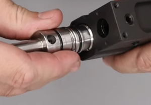
06:42 Using a pair of snap ring pliers, grip the valve stem and rotate it gently until you feel it locate in the cut outs in the block.
06:54 Add a small amount of silicon grease to the two ‘o’ rings and install over the valve. The smaller ‘o’ ring goes first and is pushed down followed by the larger ‘o’ ring.
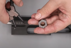
07:20 The retention nut can then be placed on top and tightened with a valve removal/tightening tool and 19mm spanner. If you do not have the tool, a set of snap ring pliers can be used.
Assembling and Installing the Regulator
Ghost Regulator Pressures
| TYPE | CALIBRE | POWER | PRESSURE |
|---|---|---|---|
| Ghost | 177 | 12 | 105 |
| Ghost | 22 | 12 | 105 |
| Ghost | 177 | 18 | 120 |
| Ghost | 177 | 20 | 160 |
| Ghost | 22 | 35 | 115 |
| Ghost | 22 | 45 | 145 |
| Ghost | 22 | 61 | 160 |
| Ghost HP | 177 | 30 | 160 |
| Ghost HP | 25 | 70 | 165 |
| Ghost HP | 30 | 95 | 160 |
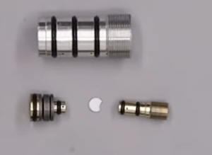
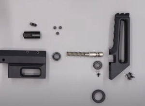
08:25 Apply a light coat of silicon grease to the ‘o’ rings on the regulator piston.
08:35 Place the white sealing disc on top of the regulator piston.
08:45 Insert the piston into the regulator body. As you push it in ensure the white sealing disc is not pinched.
09:03 Apply a light coat of silicon grease to the ‘o’ rings on the adjuster screw and then screw into the regulator body (09:10), tightening with a flat bladed screwdriver. Screw in until you feel the adjuster come to a light stop then back off a turn.
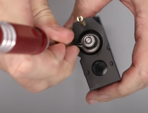
09:32 Add a small amount of silicon grease to the three ‘o’ rings on the regulator body.
09:39 The regulator body is installed into the middle hole in the front of the block using the regulator removal tool. If you don not have the tool, a set of snap ring pliers can also be used.
The HUMA regulator for the ghost is not intended for user repair, however it is possible with care to service the regulator using a repair kit purchased directly from HUMA-AIR. BRK has produce s Ghost regulator repair video which can be viewed HERE
Installing the Top Rail and Cocking Linkage
Note: The cocking arm can be located on either side of the BRK Ghost.
10:10 Insert the cocking arm into the cocking linkage on the side you want the cocking arm on (ie left or right).
10:19 From the other side, insert the retaining screw into the middle of three holes. Tighten with a flat-bladed screwdriver.
10:35 The drop down cocking handle is installed by first dropping the bolt through the hole at the back of the cocking arm; then screwing the handle in from underneath.
10:45 Add a small amount of moly grease to all moving surfaces on the block so they slide freely.
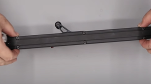
11:16 The cocking linkage can now be added to the top of the block. Place the linkage into the groove.
11:41 Insert the bush into the front hole on the cocking arm and place the top rail on the top of the block (11:47).
11:54 There are six securing screws – four M4x16 bolts, two each at the front and back. The two in the middle are M4x20. Insert the four bolts front and back and nip up with a 3mm allen key. Do not fully tighten them. One of the two middle bolts also secures the cocking arm.
12:36 Insert the cover plate to the side of the block you have not installed the cocking arm on. Ensure the small cup goes in first at the back of the slot and hooks into place. (12:45) The cover plate is secured with the second of the two middle securing bolts.
12:50 Ensure the top rail is properly aligned and tighten all six retaining screws using a 3mm allen key.
Assembling and Installing the Rear Block
13:31 To reinstal the hammer, simply slide it into the large hole in the rear of the hammer housing.
13:40 The cocking dog is installed with the post uppermost and the two grub screws pointing towards the muzzle end of the rifle.
13:52 Use a set of pin nose pliers to lightly grip the post on the cocking dog. Use a finger in the hole at the end of the hammer housing to hold the hammer in place then slide the cocking dog into the dovetail on the hammer. Use a long allen key or similar to push it all the way to the back against the hammer. Then tighten the grub screws with a 2mm allen key.
14:22 Install the bush into the back to hold the hammer in place. Align the small slot in the bush with the top of the block. (14:34) Insert and tighten the three securing screws using a 2.5mm allen key.
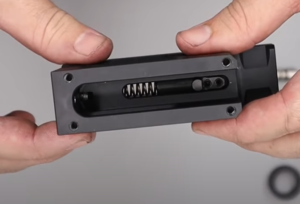
14:55 The hammer spring can now be dropped in through the hole in the bush. Ensure it is aligned with the hammer.
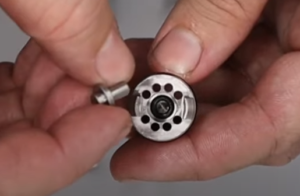
Power Wheel Reassembly
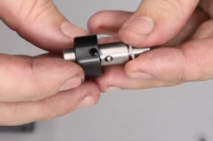
15:12 Add the inner section to the power wheel dial to the worm shaft. The dimples on the wheel should face outwards.
15:22 Line the two holes in the inner section to the power dial aligned with the track and then install the ball bearings – two in each of the two holes.
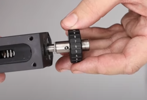
15:46 Attach the outer power wheel making sure you have it orientated correctly. (16:00) Insert the grub screw and tighten with a 2mm allen key.
16:07 Add a small amount of moly grease to the inner part of the power wheel shaft, ball bearing track and dimples.
16:38 Insert the power wheel assembly into the back of the hammer housing with the ball bearing in the shaft aligned to the top of the block.
16:55 Apply a small amount of moly grease to the ball bearing and surrounding area inside the butt section.
End Block Housing
17:16 Fit the butt part to the hammer housing and secure with the three M4x20 securing bolts, one of which will be an anti-tamper screw on 12 ft/lbs rifles, requiring the use of an anti-tamper tool or snap ring pliers. The other two bolts tighten with a 3mm allen key.
17:43 A fourth M4x24 bolt inserts into the second hole from the top of the rear of the butt pad. Tighten with a 3mm allen key.
Note: it is worth checking the power wheel rotates properly before tightening all four bolts.
18:20 Add the rubber shoulder pad by holding the square retaining nut behind the slot with your finger and screwing the pad in place using a 3mm allen key.
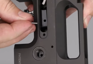
18:42 Before mating the rear hammer block to the main block, take the small 2mm pin and insert into the hole in the brass section of the trigger linkage.
19:02 Take the larger pin and place through the forward hole in the square block at the top of the main block.
19:18 Slide the rear hammer block onto the main block. (19:28) Insert the grub screw into the forward most hole at the bottom of the rear hammer block. Tighten with a xmm allen key.
19:38 The four securing M4x16 bolts can be screwed into the four holes at the back of the top rail using a xmm allen key.
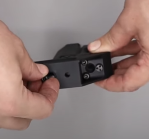
20:25 Drop the trigger cassette into the bottom of the block. You may need to pull the trigger back to get it to seat correctly. (20:38) Secure with the two securing screws in the side of the block using a xmm allen key.
Installing the Grip, Cheek Piece, Top Rail and Gauges
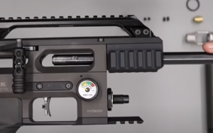
21:09 Before installing the regulator pressure and air fill pressure gauges, ensure the doughty washers are in place.
21:16 The air fill pressure gauge screws into the hole at the right side of the front of the block forward of the trigger. Tighten with a 22mm spanner. Once tightened, push the plastic collar over the gauge (21:33).
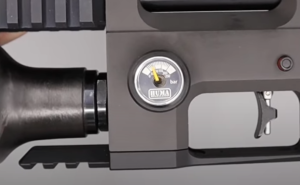
21:38 The regulator gauge – marked ‘HUMA’ – is inserted into the hole on the left side of the block forward of the trigger. Use a 22mm spanner to tighten and place the plastic collar.
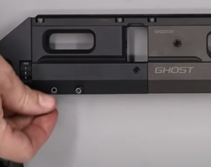
21:51 The Picatinny inter rail has an alignment rail to indicate the end that should face the muzzle.
22:00 Slide the rail onto the dovetail rail on top of the rifle and tighten and tighten the four allen bolts using a 3mm allen key.
22:25 Slide the cheek piece on to the rear of the dovetail on top of the rifle making sure it is orientated to suit right or left-handed shooters. Tighten the retaining screws using a 2.5mm allen key.
22:43 Insert the pistol grip spacer and insert into the cavity in the underside of the block. Alight the cut outs in the spacer with the cut outs in the block. (22:55) Once inserted, push the spacer back towards the rear of the rifle.
22:57 Place the grip into the cavity and tighten the screw using a 4mm allen key.
23:14 With the screw tightened, insert the long spacer and insert into the pistol grip cavity. (23:21) Return the trap door at the bottom of the grip.
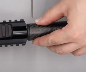
Installing the Barrel, Shroud and Pellet Probe
23:33 Insert the barrel into the block ensuring the dimple in the side of the rear of the barrel is aligned with the hole at the rear of the block just forward of the breech.
24:03 Tighten the grub screw with a 3mm allen key so as to secure the barrel.
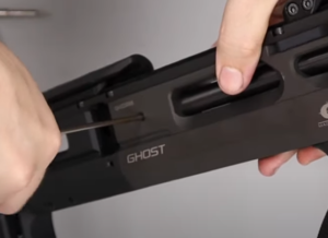
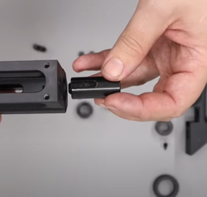
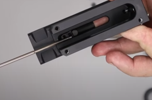
24:21 To install the pellet probe, first pull back the cocking handle. Then insert the pellet probe through the rear of the rifle (25:09). Secure with the securing screw in the side of the pellet probe block (24:52) using a 2mm allen key.
24:59 De-cock the rifle by holding the cocking handle and allowing it to return as you pull the trigger.
25:13 Insert the brass stripper into the shroud end support. Then tighten the two grub screws using a 2mm allen key.
25:29 Add the large ‘o’ ring over the end of the support and cover with a small amount of silicon grease to the ‘o’ ring.
25:39 Take the shroud rear support and ensure the two slots are oriented downwards on the barrel. (25:53) Slide the shroud end support over the barrel and push it back almost as far as it will go, leaving just a small gap, then secure with the two short grub screws using a 2.5mm allen key. Apply a light amount of silicon grease to the ‘o’ ring.
26:30 Screw the stripper onto the front of the barrel, but only hand tight.
26:39 Now add the carbon fibre shroud over the stripper and align the two holes with the two holes in the rear support. Insert and tighten the two long grub screws using a 2.5mm allen key.
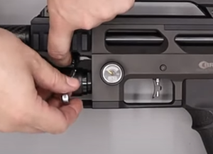
Gassing Up the Rifle and Adjusting the Regulator
27:15 Screw on the air bottle and then re-pressurize the rifle.
27:26 Assuming there is air in the bottle, you will see the pressure register on the air fill pressure gauge. However, the regulator pressure gauge will indicate zero (27:33).
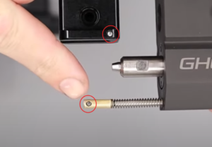
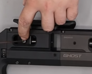
27:39 The regulator pressure is reset by adjusting the regulator adjust screw at the front of the rifle with a flat-blade screwdriver. The screw is located just above where the bottle connects to the block.
NOTE: sub 12 ft/lbs rifles will be fitted with an anti-tamper sticker covering the regulator. It is illegal to adjust an air rifle to deliver more than 12 ft/lbs unless appropriate licensing is in place.
28:00 To increase regulator pressure, the adjuster screw must be turned anti-clockwise. This can be done when the rifle is pressurized. However, regulator pressure cannot be decreased (turning the adjuster screw clockwise) when the rifle is pressurized as this will damage the regulator. Instead, you will need to de-pressurize the rifle fully, make the adjustment and then re-pressurize. This process will need to be followed as you make further downward adjustments.
28:32 Turn the adjustment screw anti-clockwise noting the reading on the regulator pressure gauge. If you noted the regulator pressure when disassembling the rifle you should aim to re-set it at the same level. It is advisable to check exact power output using a chronograph.