BRK Ghost Disassembly Guide
Workshop procedures to disassemble the BRK Ghost PCP (all model variants)
All BRK Brocock PCP air rifles are engineered to the highest standards. However, like anything mechanical, they require servicing and, even, repairs (in and out of warranty). The aim of this guide and the accompanying step-by-step videos is to specifically help you undertake work on the BRK Brocock Ghost (all variant models).
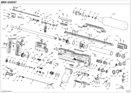
Below is an exploded diagrams of the standard BRK Ghost model. Usually, only the stock, barrel length and air bottle options differ. There is also a list of tools that you will need.
Important: Compressed air is dangerous! So you should only use this guide if you are an experienced gunsmith and conversant working with compressed airguns. If you do not consider yourself competent, please take your rifle to you local authorised BRK Brocock Service Center or contact the factory for advice.
Before you carry out any work on a BRK Brocock PCP air rifle, you must ensure it is not cocked, not loaded and completely empty of air. And you must always follow all safe working practises.
BRK Ghost Rifle Disassembly Guide – Resources
- Tools you will need
- Removing of the bottle and de-gassing the rifle
- Removal of the barrel and pellet probe
- Disassembling the shroud
- Removing the grip, cheek piece and top rail
- Removing and disassembling the regulator
- Removing and disassembling the hammer housing
- Removing the top rail and cocking linkage
- Removing and disassembling the valve
- Removing the bottle rail and fill port
- Removing the trigger
Tools You Will Need
- 1.5, 2, 2.5, 3 and 4mm allen keys
- Snap ring pliers
- Long nose pliers
- Open ended spanners: 19 and 22mm
- Valve removal tool
- Regulator removal tool
- 3-pin anti-tamper removal tool
- Tweezers
- 6mm flat blade screwdriver
- ‘o’ ring pick
Before you start, it is advisable to make a note of the regulator pressure in your rifle (0:57).
Removing of the Bottle and De-gassing the Rifle
01:00 Remove the magazine and dry fire the rifle into a safe back stop to ensure it is not loaded.
01:14 De-gas the rifle by unscrewing and removing the air bottle. Note that there will be a light hiss of air.
01:26 Check the bottle pressure gauge shows empty.
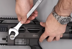
01:30 Check the regulator pressure gauge as it will likely indicate there is still air within the regulator. To remove it, simply dry fire the rifle in a safe direction until the gauge reads empty. Alternatively, the regulator pressure gauge – marked ‘HUMA’ – can be loosened with a 22mm spanner (01:43). Again, you will hear escaping air. The gauge can then be removed.
02:08 Remove the bottle pressure gauge using a 22mm spanner.
Removal of the Barrel and Pellet Probe
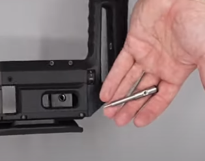
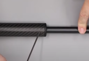
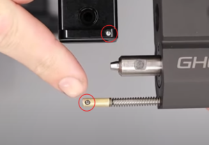
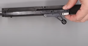
02:18 To remove the barrel, loosen the grub screw at the rear of the rifle just forward of the breech using a 3mm allen key. The barrel will then pull loose.
02:34 To remove the breech probe, cock the rifle then loosen the allen screw in the block at the side of the breech block accessed through the side of the action. Use a 2mm allen key.
02:45 With the screw removed, tilt the rifle rearwards and the pellet probe will fall out of the back of the action. (02:49) De-cock the rifle by holding the cocking handle and pulling the trigger.
Disassembling the Shroud
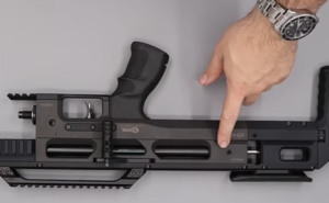
03:05 Remove the two grub screws in the base of the shroud using a 2.5mm allen key. This will allow the carbon fibre shroud to pull off the barrel.
03:27 Removed the front support and stripper for the shroud. The front support is removed by inserting a bar – ideally plastic – for leverage and then undoing.
03:45 The brass stripper can be removed by first taking off the ‘o’ ring and loosening the two retaining grub screws with a 2mm allen key. This will allow the brass section to be pushed clear.
04:05 The back shroud support is removed by loosening the two securing grub screws with a 2.5mm allen key. The support will then slide off the barrel.
Removing the Grip, Cheekpiece and Top Rail
05:13 The scope intermount rail is removed by loosening the four allen bolts using a 3mm allen key. The top rail will then slide off the rifle.
05:26 The cheekpiece is removed by loosening the two grub screws on the top using a 2.5mm allen key.
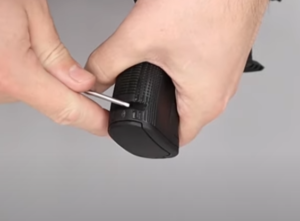
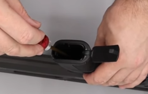
05:40 The pistol grip is removed by popping open the cap on the bottom of the grip using a flat head screwdriver in the slot just above the flat bottom. Remove the plastic insert and then undo the retention screw using a 4mm allen key.
05:57 Remove the plastic spacer underneath the pistol grip.
Removing and Disassembling the Regulator
NOTE: Sub 12 ft/lbs rifles will have an anti-tamper sticker covering the regulator.
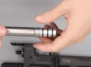
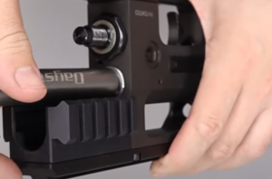
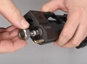
06:15 The regulator is removed using a Daystate/BRK regulator removal tool. If you do not have a removal tool, you could use a set of snap ring pliers.
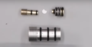
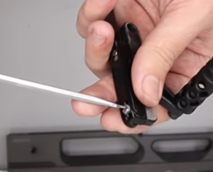
06:49 The adjuster screw can be removed by unscrewing with a flat head screwdriver.
07:01 Put your finger over the hole left by the adjuster screw to avoid the white sealing disc falling out.
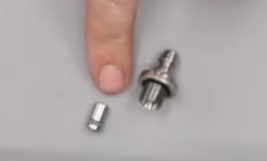
07:09 Take and M4 bolt and screw it into the other end of the regulator. This will allow you to pull the piston and the sealing disc out from the base of the regulator.
Removing and Disassembling the Hammer Housing
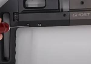
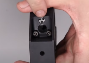
08:38 To separate the back part of the block from the main block, start by removing the two screws at the bottom of the back block using a 2.5mm allen key.
08:50 Stand the block upright and gently pull the trigger to loosen a cassette at the rear of the block.
08:57 Remove the grub screw at the front of the back block using a 3mm allen key.
09:02 Remove the four rear most securing bolts in the top of the block using a 3mm allen key.
09:13 The rear block will now pull free from the main block.
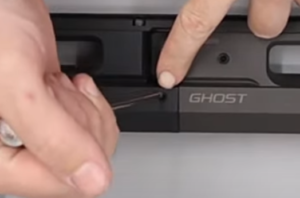
09:20 Take care to not lose the 2 small pins in the brass trigger linkage and rear block. They can be pushed out and put somewhere safe.
09:35 Remove a second pin from the pellet probe block.
09:52 Remove the butt pad by undoing the screw at the back with a 3mm allen key. Put your finger on the other side to prevent the square nut falling out and being lost.
10:06 Separate the butt pad section from the rest of the rear block by undoing the two allen bolts at the top of the butt section using 3mm allen key. A third screw is accessed via a hole a third of the way down the butt block (10:19). A fourth bolt at the top of the butt block is a three-pin anti-tamper bolt on sub 12 ft/lbs rifles and will need a three-pin anti-tamper tool to be removed.
10:50 With all four bolts removed, the butt section can be removed.
Disassembling the Power Adjustment Wheel and Hammer
10:57 The power adjuster wheel and hammer spring can be pulled free from the other half and the back block along with the hammer spring.
11:05 Take care to not lose a small ball bearing in the stem of the power wheel.
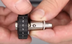
11:22 The power wheel can be further disassembled by using a 2mm allen key to remove the grub screw in the dial to remove the outer housing from the inner section. Be careful to not lose the four ball bearings underneath.
12:07 The bush at the back of the block is removed by undoing three allen bolts using a 2.5mm allen key.
12:23 The hammer is removed by using a 2mm allen key to loosen the two grub screws. This will allow the hammer to be tipped out of the block along with the cocking dog.
Removing the Top Rail and Cocking Linkage
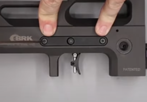
12:56 The top rail is removed by undoing the six securing screws on the top with a 3mm allen key.
13:19 Take the cover plate off then lift the pellet probe assembly off the block (13:23). Take care to not lose the small bush in the hole at the front of the cocking lever assembly (13:28).
13:37 The cocking arm is removed from the pellet probe assembly by undoing the screw at the rear of the cocking arm using a flat headed screwdriver. This will allow the cocking arm and cocking handle to be pulled free.
13:55 The cocking handle can be removed from the cocking arm by undoing an allen bolt in the bottom of the handle using a 3mm allen key.
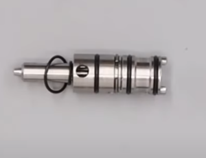
Removing and Disassembling the Valve
14:19 To remove the valve, use a valve removal tool with a 19mm ring spanner. If you do not have one then a pair of snap ring pliers will suffice.
14:37 Use a snap ring pliers to lightly grip the valve and then gently pull it from the block.
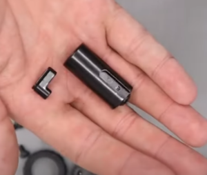
14:57 Remove the two ‘o’ rings from the front of the valve then locate the retaining ring in a recess in the middle of the valve and rotate it to one of the cut outs so it will separate (15:02).
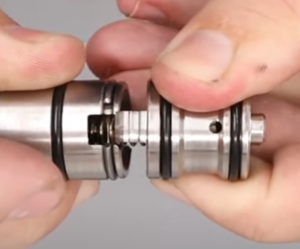
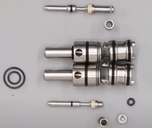
15:12 The valve return spring and valve pin are removed by pushing a small allen key through the stem end.
15:23 Use a pair of long nose pliers to remove the plug from the bottom of the rear part of valve assembly. (15:29) A small ‘o’ ring located in the base can be hooked out.
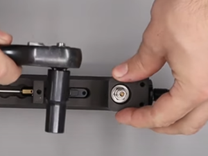
Removing the Bottom Rail and Fill Port
18:47 Remove the bottom rail from the underside of the main block by loosening the three screws using a 3mm allen key. This will allow you to lift the bottom rail away and pull off the filler valve dust cover.
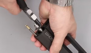
19:00 Use a deep 10mm socket to remove the fill port valve.
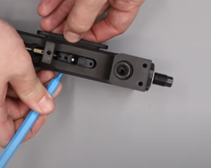
19:17 To remove the one-way valve use an air line blower to momentarily pressurise the unit from the top to force the valve out from the bottom. If you do not have an air line blower, you could also use a dive cylinder to connect to the valve. Take care to provide a very short burst of low-pressure air and ensued the valve is placed on a hard surface or pointed into a safe direction that will ideally capture the valve when it is released.
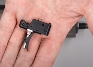
Removing the Trigger
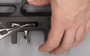
20:20 Remove the two screws on the trigger plate on the left side of the block above the trigger using a 2mm allen key.
20:28 Use a plastic ‘o’ ring pick and push through the safety catch from the right side of the block. This will allow you to remove the plate and the safety catch again from the other side.
20:45 Place the block on its right side and remove the trigger pin through the cavity exposed by the trigger plate using a set of long nose pliers. (21:00) With the pin removed, the trigger blade and trigger assembly will lift clear of the block. Take care to not lose the small spring and brass cup.
21:22 Use a small flat head screwdriver to remove the plastic cover by sliding it rearward down a channel on the underside of the block.
21:30 This will allow you to lift the trigger linkage.
22:06 To remove the bottle valve you will need to use a 25mm spanner. Note the valve is secured with Loctite at the factory as it is not intended for removal for routine service.